For EMF camp 2024 I'm making an electrically driven, tracked tricycle (it's probably not a tricycle, if you count the tracks wheels it has 7, but a septacycle doesn't sound right...).
As part of this build I need a few parts in 4mm plate steel that have well aligned bends. I've been using the sheet metal system of Fusion 360 to design these, and it's 'unfold' function to give me a 2D drawing of the cut out lines of the part.
I added a line along the centre of the fold to this. I'll create a groove along this line to locate on the bend knife of my bending machine and will create the groove using a none piercing cut on my plasma cutter.
The groove was created with about 50% of the power of a piercing cut using my ArcDroid CNC plasma,
And then the part was cut out with a piercing cut.
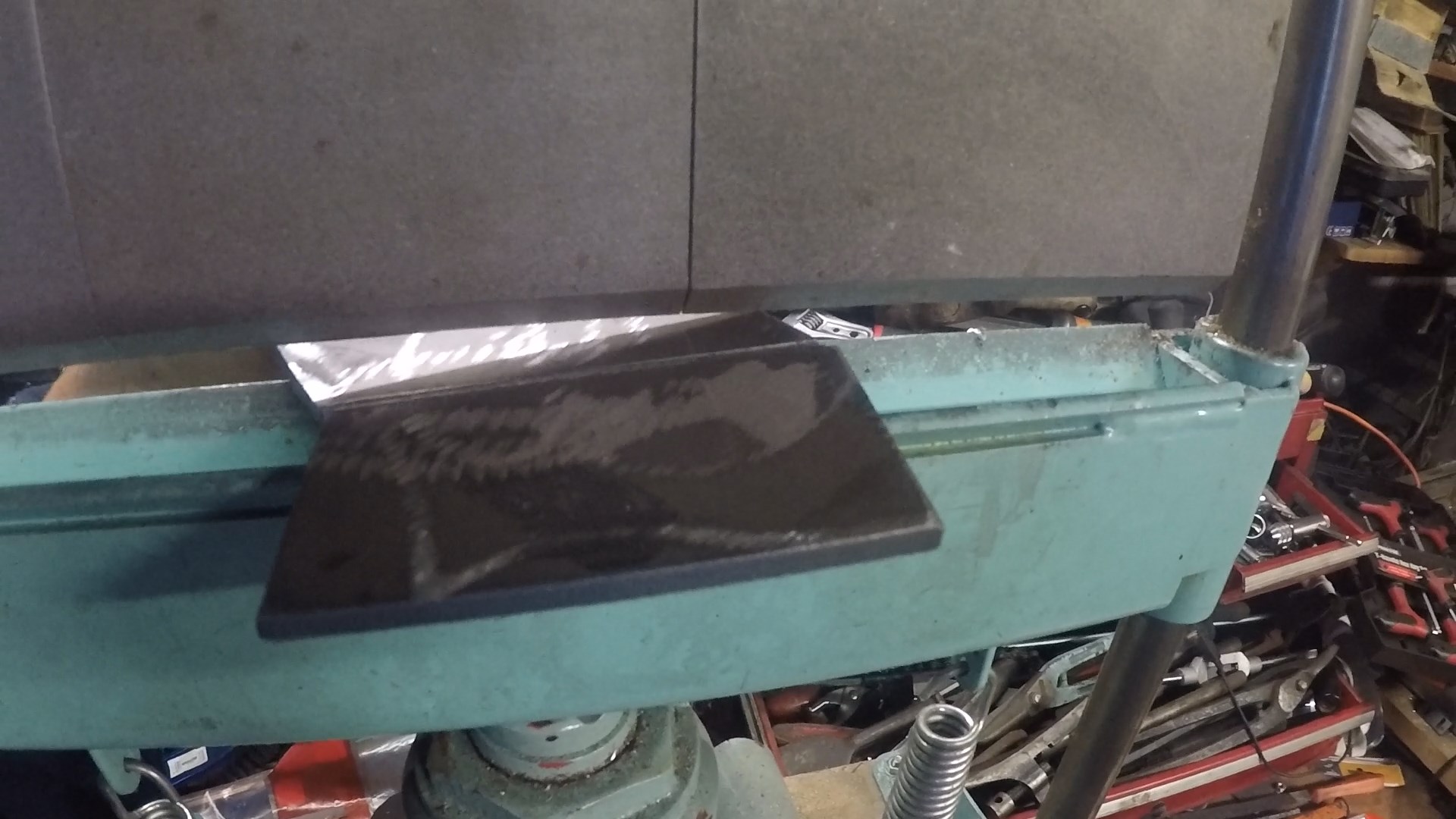
I then aligned this groove onto the bending machine and started the bend.
It came out well. I'll weld over the groove to make sure it's not weak.
The larger plate is more problematic. It has two bends in opposite directions. I can only create the grooves on the 'cut' side of the plate. The second groove will be facing downwards and won't be able to engage with the bend knife.
I used the technique above to create the grooves and cut out the part.
To solve this I designed a 3D printed alignment block. It has a triangular form to centre it it the V groove of the bender (and align it directly above the bending knife) and a sharp ridge on top to locate in the groove of the workpiece,
With two of these in place, it's easy to align the groove with the ridge.
The bending almost maxed out my puny hydraulic bender.
And the guides are destroyed in the process. They only take 10 minutes to print two though.
The opposite bend blew out the plate slightly but I'll just reinforce this with the welder.
Overall though, I'm very pleased with the end result and would certainly use this technique again.
I've started making an EV to take to EMF camp 2024. It's going to be driven by snowmobile\ATV tracks which I got from AliExpress.
Snowmobile/ATV tracks
The track units are driven by a splined shaft. As this is a custom build I was going to have to make this for myself.
Gonna need splines for this.
My plan was to use a HV6 rotary table on the mill and dividing plates. This is a machine chuck mounted onto a rotating table. By turning a handle with a 90:1 reduction ratio the chuck angle can be accurately controlled. Dividing plates are used to allow number of positions to be defined such that the chuck can be configure to perform a 360 degree rotation in (say) 23 stages. i.e. 360/23 degrees per stage. At each stage a single spline would be cut.
Rotary table set horizontally with dividing plates.
The rotary table would be mounted horizontally on the milling machine and a slitting saw run horizontally to cut each spline.
Reading the HV6 manual it occurred to me that the dividing plates might not work out for me as they involve counting full and partial rotations. This is the sort of thing a microcontroller would be great at and is quite similar to the Leadscrew Buddy I created for my lathe.
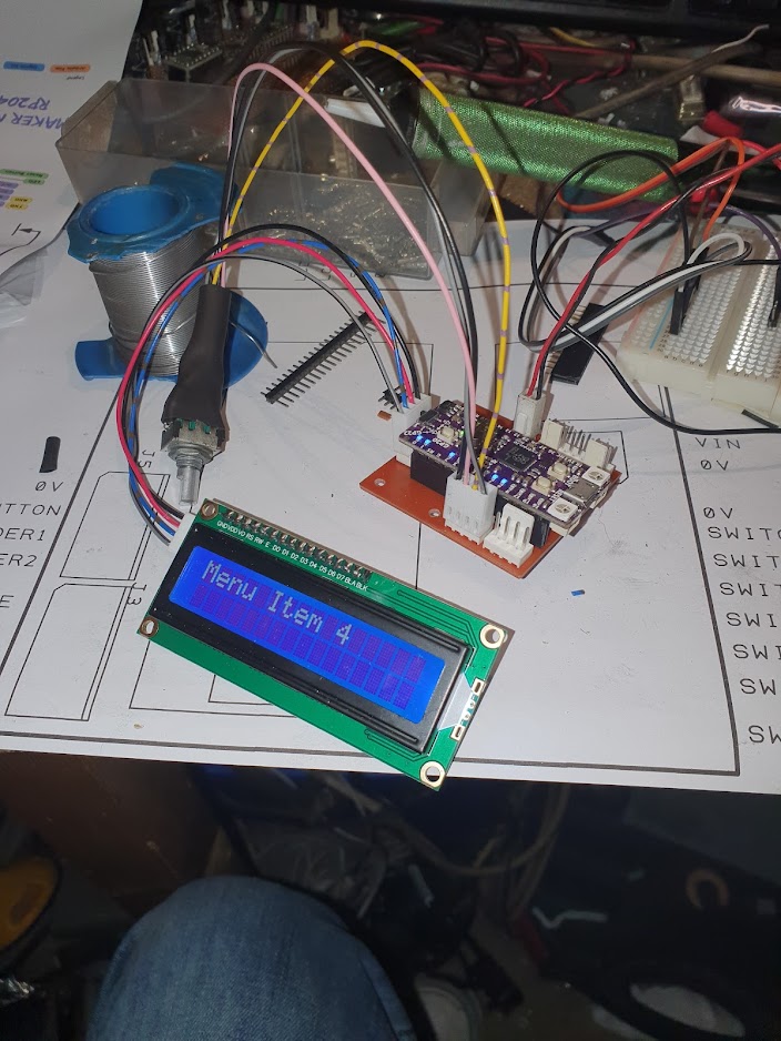
I designed a simple circuit to use a RP2040 to drive a stepper motor with a LCD display, a few buttons and a rotary encoder for user input. I chose a MakerNano RP2040 board as it is fully supported by the Arduino IDE and was less than £10 at the time of writing. It's also 32bit. Although using integers the numbers in the software will be quite large so something more powerful than an Arduino Nano seemed appropriate.
Simple RP2040 circuit.
I hashed together a circuit with stepper driver and motor for a proof of concept. The software was written in C++ on Visual Studio 2019 with the Visual Micro extension.
Working on the encoder driven menu system
And using Design Spark for the schematic allowed me to quickly create a PCB....
PCB designed with Design Spark
Which I milled on my CNC router: Bertha
Bertha at work.
I created the GCODE using FlatCam. What a great piece of software this is. Routing, drilling and milling operations all created in one application.
PCB came out OK.
Post milling PCB
The software allows the rotary table handle turns per revolution (defaults to 90 which is pretty standard) and the stepper motor micro steps per revolution to be set by the user. These are then stored in EEPROM. The user simply dials in the number of splines required and the software calculates the number of steps per spline. Next/Previous controls allow the table to move when the current spline has been cut and the LCD displays the current spline number and total spline count.
With a table reduction ratio of 90:1 and 1000 steps/revolution micro stepping there are 90 x 1000 steps per table revolution. 0.004 degrees per step. That should be enough (and the 32bit CPU won't break a sweat).
I also designed a 3D printed case and CNC routed fascia.
The box
The fascia was cut from aluminium and v carved with control labels. I squeegeed in black acrylic paint:
Acrylic paint after squeegee
Allowing the excess to dry a paste of sodium bicarbonate easily cleans the surface. With a light spray of clear varnish as a sealant it looked pretty good with the controls fitted.
Not bad for home made...
I'm using a stepper driver that I had lying around. Of the two I had this one alone worked. The other driver indicated 5V was required at the inputs and the RP2040 runs at 3V3. The working driver didn't mention 5V anywhere.
With the box printed the parts were fitted and wired. I'm using 24V dc power and the 5V linear regulator on my PCB would get too hot at this voltage. I added a small switching regulator board from AliExpress to drop this to a more reasonable 9V feed into the PCB.
Everything fitted.
With the fascia and controls fitted it's looking OK.
There are 23 x 60 degree spines required on the shaft. I ordered an appropriate V groove cutter from AliExpress:
60 degree V groove cutter
I dialled in the required 23 splines and had a trial run on Delrin.
Test piece looks good
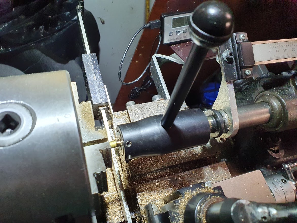
This turned out so well I decided to try the actual drive shaft. I'd bought a suitable piece of steel bar from Noggin End Metals and had already put some time into it on the lathe getting it prepared.
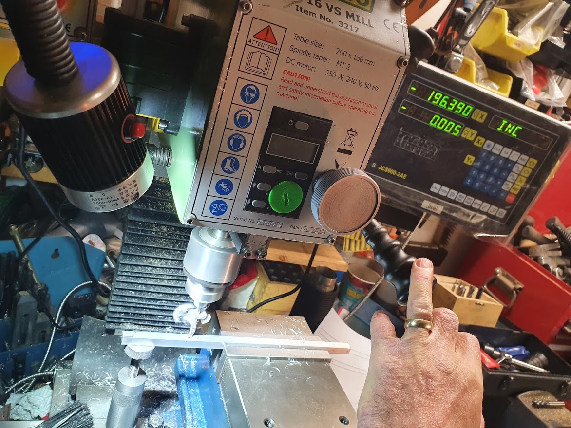
With it installed on the mill each spline took about 10 minutes to complete as my small machine can't handle deep cuts.
Cutting the splines
After each spline pressing the Next button moves the workpiece into the new position.
Did it work. Well, the proof of the pudding is in the eating..........
A couple of years ago I converted a standard kick scooter to be electric for my younger son. I had the motor controller, battery and motor in a single unit simply bolted to the rear of the donor scooter. He loved it!
However, whilst recently browsing AliExpress I came across these, a dual brushless motor drive unit for mountain boards.
It just so happened that my oldest son got the taste for mountain boarding about 5 years ago, then lost interest in it and the board has sat in the shed since. With #2 son spending quite a lot of time on the scooter, and me trailing him on foot I thought it might be time to awaken my skateboarding talent that has lain dormant since the '70s.
I ordered a rear wheel only kit , battery and controller and bolted them together.
No surprises here. Just a few holes and a bit of wiring and I was off.
Problem with this is #2 son realises the mountain board is significantly faster than the scooter and confiscates it.
This does of course mean, once again, I'm trailing him on our outings..although at least I can use the scooter. This was less than ideal given his new speed, so the only course of action is to put the same mountain board motor unit on the back of the scooter to make an e trike.
As the original had an all in one design, I just CADed up a replacement with the dual motor drive instead.
I used a combination of manual milling and CNC milling on DIY CNC to create the new parts.
15mm aluminium plate for cross pieces....
Bolted to a 6mm aluminium plate....
Which in turn bolts to the scooter body. The electronics sit in a box cavity to keep them safe.
The mountain board controller is a bluetooth hand held device. It has a simple self centering thumb throttle potentiometer which you push up to move forwards and pull back to e-brake. In particular, it has a nice feature where if you release the throttle then immediate push push it up again, the motor controller switches to a faster motor speed, kind of like a gear change.
I quite liked the idea of this, but decided that using a traditional scooter twist throttle it would not be easy to operate it fast enough to get the same operation. I then realised I could achieve a good alternative by using two thumb throttles. One on each side of the handlebars. Right side for brake and left side for throttle.
To make the two potentiometers act as one I was going to need something more than simple wiring to connect them to the original handset. I designed an Arduino circuit to take the inputs from both throttle and brake pots and with some software filtering drive an electronic potentiometer which I simply used to replace the one in the hand held controller.
The board also has a DFPlayer mini on it as my son wanted a horn/siren facility as well.
I designed the schematic with my go to PCB package: Design Spark.
And a PCB:
Which I routed on Bertha, my DIY CNC:
With the PCB made up and a test jig for the thumb throttles I was ready for a test. Here I demonstrate the controller action of the mountain board controller and my version of it. I was initially planning to replace the 3.7V LiPo on the handset controller with an Arduino controlled power supply to replace the battery and the power switch of the handset, which was one of those press to power on, press and hold to power off types.
Luckily, I found that the handset is quite happy to power on with just 5V from the micro USB charging port, so in the end it just shares the 5V feed with the Arduino.
The software always prioritises the brake function over the throttle and the braking is or variable strength. I also added a digital input to the Arduino so that I could connect up a traditional brake handle with a built in switch to apply full braking when it is applied.
Happy that the electronics and software were OK. I designed a simple 3D printed box to house the handset, Arduino and a switching PSU to drop the 42V battery down to 5V.
This was 3D printed with some clamps to hold it to the steering column.
I also transplanted the original controller battery voltage meter into the new housing and added a key switch.
So with everything together it's time for a trial run, which of course I didn't get to do. I just rode wingman on the e mountain board. The smile at the end says it all!.
I'm happy with the way this turned out. It's great fun to ride and it's certainly different from the run of the mill two wheelers everyone else has.
I was introduced to the idea of a none sequential clock by Bob at Hacman. The idea is two large gear rings with hours and minutes engraved on them driven by stepper motors. The numbers though, are out of sequence, and so each new minute and hour involves movement of the rings in a different direction and distance.
A picture paints a thousand words:
Bob's clock at Hacman.
I've always had a fascination with clocks, and I really liked the idea of this one. The rings are suspended from smaller gears which are directly attached to the steppers. It's a bit big though, probably 1.2m in diameter. I thought I'd try making one a bit smaller.
My original plan was to laser cut the gears, using plywood for the rings and acrylic for the driving gears. To make it a bit more visually exciting, I introduced some idler gears on both rings. The idea being that a single gear at the top would drive the ring, and the ring would drive the idlers (this turned out to be an idea doomed to fail...).
I then imported the 2D output from both these into my CAD package, and from here went straight to the laser cutter.
I was really pleased with the way it looked. This was in 2015. And the project just stopped.
First design.
So along comes 2020, and like many others I was looking for something to occupy me, and this seemed like a good place to start.
I started looking at electronics to drive the steppers. I decided to use a Wemos D1 mini as the controller as the wifi module would allow me to use NTP to automatically set the clock without user interaction. All that would be needed would be the WiFi credentials and the daylight savings settings, and a connection to Google's NTP server would do the rest.
Bunging some Pololu DRV8825 stepper drivers on a breadboard got me a platform on which to start the software development.
Untidy, but it works.
First job was to get the steppers running. I used Visual Studio 2019 with the Visual Micro plugin. The software was developed using the Arduino board support for the Wemos.
I used the accel stepper library to create the motor step pulses. This library handles the acceleration/ deceleration for multiple motors, and uses the concept of a numeric position for the motor spindle which can include multiple spindle rotations.
After getting this running , it soon became clear that the small idler gears were causing the hour and minute rings to jam. The single, small cog on the stepper spindle is OK driving the much larger number rings, but these larger rings driving multiple, smaller gears caused far too much friction.
I resigned myself to losing the idler gears, and concentrated on implementing software to move the rings to the correct position.
Each ring is represented by an array of integers, each specifying the distance in steps to the next number. I began by running test software to count the minutes from 00 to 59 using a mocked clock interface which increments the minute as soon as the ring stops moving.
The idea is to have the clock find the '00' position using a magnet and hall effect sensor, then total the number of steps from '00' to the current minute, then move that many steps. Initially I set the ring to 00 by hand.
With the minute ring done, similar code was used for the hour ring, just with a different array of steps per digit.
Somehow I decided the wooden clock looked a bit boring. So I decided to go for steampunk style look. The rings were replaced with clear acrylic, with the numbers to be illuminated from behind, the drive gears from brass.
I'd originally thought of it being a wall hanger but changed it to a free standing device during the re-design. A wooden base with an internal aluminium frame supports a curved top. The rear was to be laser cut birch ply with ventilation slots.
CAD view of the case.
The rear of the case.
First the brass gears. These were machine on my CNC router from 6mm brass plate. At first I thought to keep the acrylic rings away from the back plate by including a disk into the rear of the design.
This caused problems as the teeth of the ring sometimes caught on this, causing a jam. The solution was to replace it with an acrylic disk 2mm thick and of a larger diameter, and simply bolt this to the back of the gears with countersunk screws.
I was pleased with the way both drive gears turned out. I added an acrylic plate at the front to prevent the rings from slipping off the gears. The number fascia plate will prevent this too, but it means I can run the clock without the plate fitted.
The larger one had enough space for the obligatory time based Latin inscription (I spent 5 bloody years learning Latin and I intend to use that knowledge at least once.) The text was laser engraved, then filled with black acrylic paint.
After the paint has dried, a quick polish with a paste of sodium bicarbonate clears away any residue.
Brass Cogs.
For the curious it translates to "Time, commander of all things".
The current hour and minute digits are isolated from the rest of the numbers by slots cut into the numeric fascia plate. The original intention was for this to be birch ply cut on the lasercutter.
Laser cutting the wooden fascia.
The wooden fascia.
The new style demanded brass.
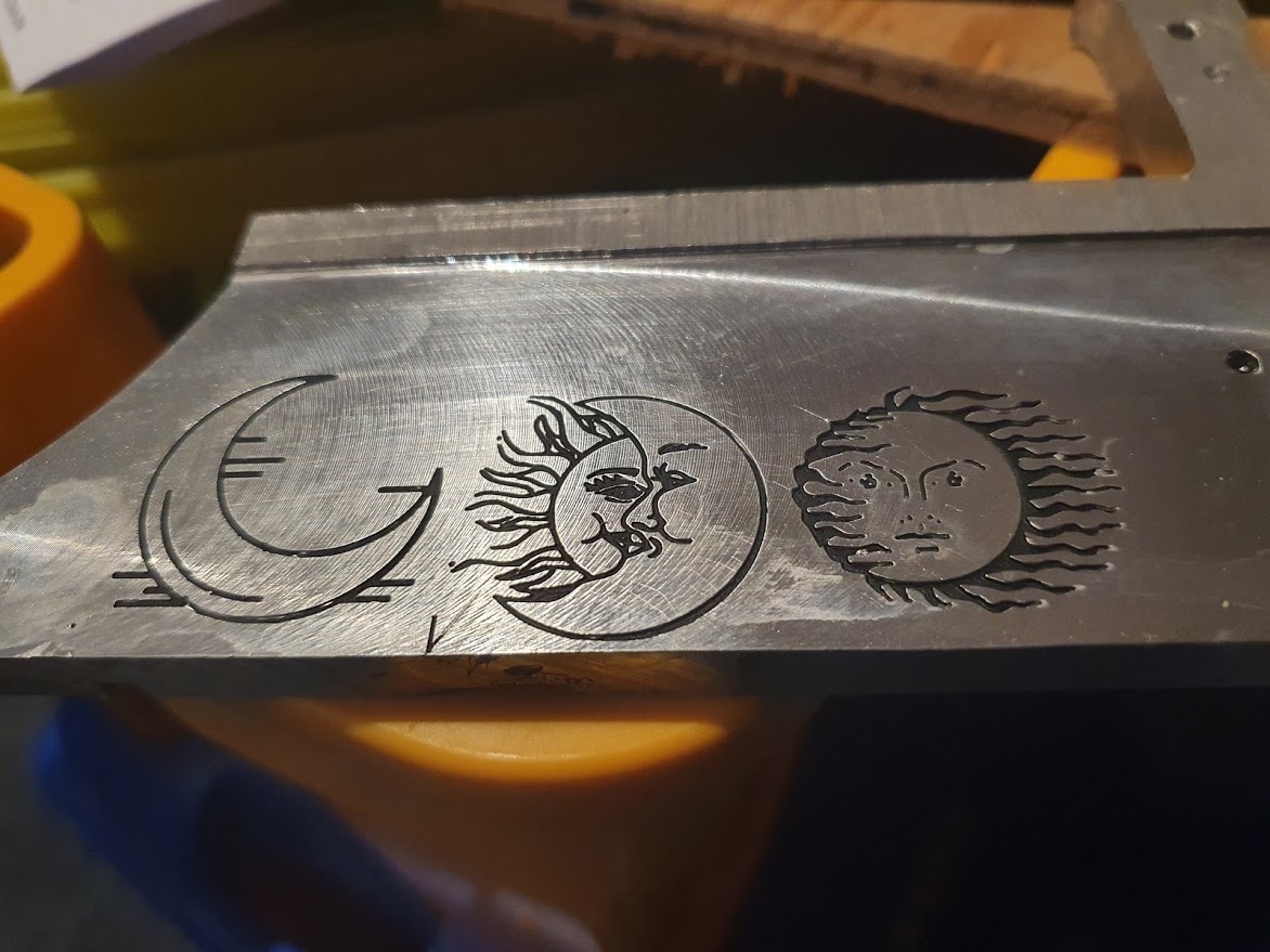
I wanted to engrave the fascia with some time themed motifs. I found a few I liked, and experimented engraving these into a 1mm sheet from ebay. The material for the real fascia is 3mm brass plate at £15 each so I wanted to check the result before committing.
I used a 0.2mm PCB engraving bit on the router. The step down was set to 0.1mm and the feed rates really low (10mm/s), with a splash of cutting fluid. The plate was simply stuck down with double sided tape to the sacrificial bed.
Test filling the engraved brass.
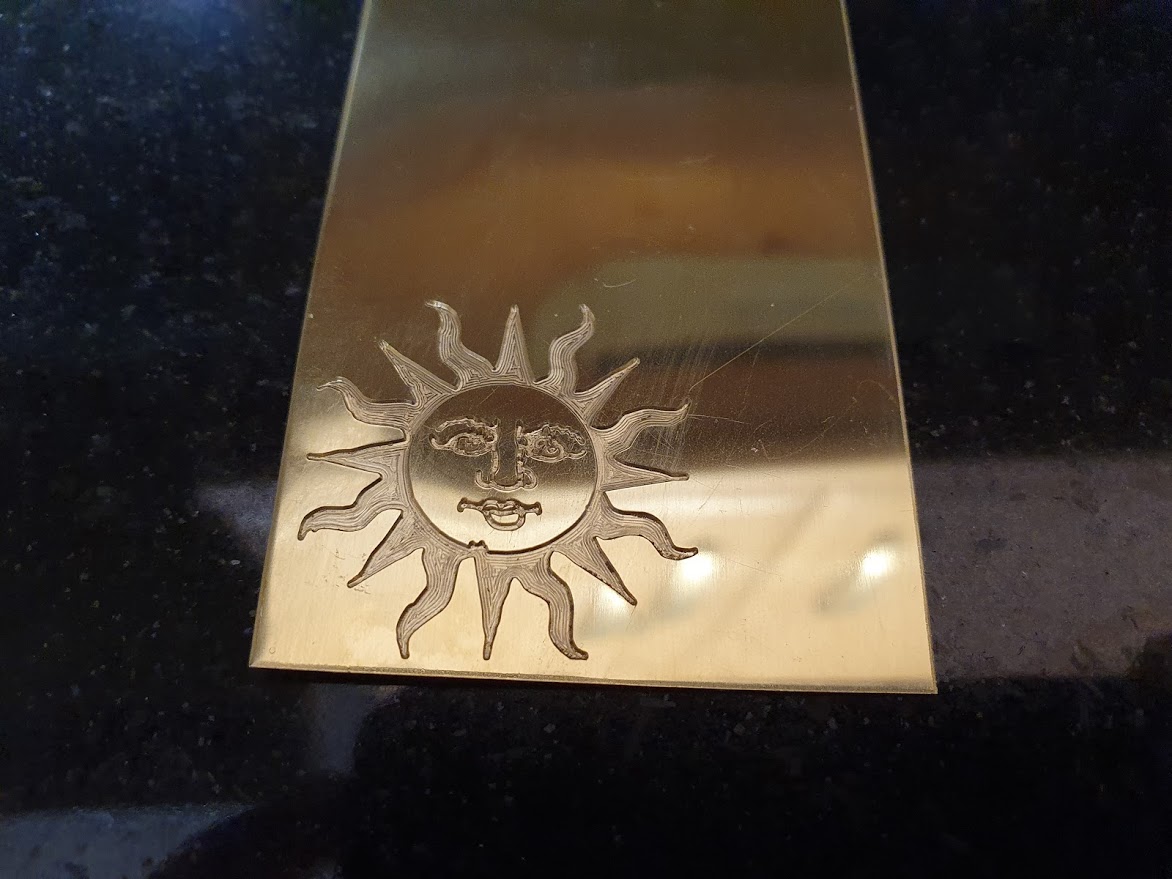
Initially I was unsure if I wanted to fill the engravings with black paint to highlight them. In the end I decided not to. Time to commit to the real thing:
Really pleased with how it turned out.
Brass fascia after engraving.
The electronics
Using DesignSpark I created a PCB for the Wemos and the stepper drivers.
PCB in DesignSpark.
I used Flatcam to machine the board on the CNC. The last double sided design that I made for Leadscrew Buddy used tinned copper wire between vias for the top layer. This time I tried the true double sided routing feature and it worked brilliantly. It was tinned with a tinning solution from ebay.
Double sided PCB CNC routed with Flatcam.
The next PCB needed was one to mount the hall effect sensor and some LEDs for the acrylic back illumination. These were simple single sided affairs initially using 5mm orange LEDs for that 'valve glow' look.
5mm LEDs not good enough.
The current surface mount current limiting resistors and hall effect device are underneath. I'm using neodymian magnets in the rings to indicate the home position and the magnetic field from these will go straight through the PCB.
I also added a small MOSFET to give me control over the LEDs.
When mounted, these didn't work very well at all. The lens of the clear LEDs gave such a tight focus at short range that the light was not sufficiently diffused within the acrylic ring to illuminate the engraved numbers. I redesigned the PCB to use two banks of four surface mount LEDs. I also dropped the FET, deciding I didn't really want to control the LEDs after all.
LEDs are great but resistors too hot.
This gave much better illumination of the numbers.
But, although rated sufficiently, the current limit resistors were getting much hotter than I would like. I made a third board with one resistor per LED. Having the router makes it so easy to quickly turn around changes like this.
I would have got away with it too, if it wasn't for those meddling kids....
Showing off my prototype creation to my teenage offspring was met with: "Yeah, it's OK but that whining noise is terrible. Are you trying to keep us away?"
Hmmmm.
The noise they could hear was the stepper drivers applying holding current to the motors. Being ancient the frequency was way above anything I could hear. Trouble was, I'd hard wired the drives to be permanently enabled. So, I re designed the Wemos board to have the stepper enable under software control. While I was at it, I replaced the 7805 voltage regulator, which was also getting hot, with a small switch mode regulator from Murata.
With the new PCB in place, the kids were (less) whiny.
Up to this point, I'd been testing with neodymian magnets held into holes in the rings with insulating tape. The silver of the magnets was distracting so I turned some small brass plates to cover them up. These and the magnets were held in place with epoxy.
Brass plates hide neodymian magnets.
The Clock Case
The base of the clock was made from an old chopping block donated by a friend. Unsure what wood it is, but it seems reasonable quality. It was CNC machined, stained and varnished.
The CNC routed base stained and varnished.
The holes are for M4 brass inserts which fasten the clock frame. These were pushed in with the milling machine quill.
Pushing brass bushings in with mill quill.
The case frame is formed from 9mm square aluminium bar.
The frame and base CAD.
The straights were machined manually on my vertical mill from drawings.
Shaping one part of the frame.
The partial frame mounted on the base.
The curved sections of the frame were the biggest challenge. I could have CNC routed them from 9mm aluminium plate, but this would have been expensive and wasteful. So the decision was made to get a ring roller.
I don't have room for a large one, and the cheaper Ebay offerings did not inspire me until I found Cyclops Designs in Sheffield. They make small rollers good for up to 10mm square. They are made to order and I found it to be of excellent quality.
So began my first ever experience of using the ring roller.
Cyclops Designs ring roller in action.
This was about as difficult as I imagined. The ring roller performed well, but I was a novice trying to match a CAD designed part. I took some time to make two semi circular pieces of the correct radius.
Once made though, I stuck a 2D print of the hole locations to each piece to be punched, drilled and tapped to M3.
Paper template helps to align holes.
I had originally envisaged these bolted to the rest of the frame with counterbored holes hiding the screw heads. Getting the angle right on these in the mill before drilling was way too daunting so I laser cut a copy of the front plate from scrap wood. This was clamped to the frame with the arcs held in the correct position, then TIG welded.
My TIG welding skills are not noteworthy....
Arc has been welded to case frame.
It was still a bit off so I got the sander to it.
Cleaning up my amateur ring rolling.
The final part of the case was the side piece that curves from one side to the other. For this I used flexible 3mm plywood. This piece needed holes aligning with matching holes in the frame. I used a transfer punch for this.
2.5mm transfer punch used to set hole positions.
Again this wood was stained and varnished.
To finish the case off, four brass feet were turned on the lathe. I modified the Leadscrew Buddy software to give me a step function software. A step distance is set and when the function is activated the carriage is moved the step distance from the current position. This makes producing multiple parts of the same length a breeze.
For added retro I laser cut some self adhesive green felt for each foot.
All the old clocks I have have felt pads.
The feet are held in place with M4 bolts into more brass inserts. I couldn't machine these at the same time the base was made as they are on the underside, so I knocked up a small jig to help me align the feet.
Simple jig to position the foot.
Up to this point I had been using standard steel bolts to hold everything together. These were starting to clash with the brass, and in some cases were just too big and needed trimming.
Ugly steel screws on brass cog.
I decided to turn a full set of screws for all the outward facing fittings. For more steampunk the obvious, and easiest screw head style was slotted cheese. These are available to buy, but I couldn't find any with the old school look I wanted. All brass fittings also removes the chance that the magnets will stick.
Again, Leadscrew buddy helped me turn down brass bar to the correct size. The threads were cut with a die and holder on the lathe.
Cutting a thread onto a screw.
And the slots were created with a slitting saw on the milling machine.
Cutting the slit in a brass screw head.
Also made were some brass stand offs to hold the brass fascia away from the back plate. And so after several hours in the workshop.
A selection of the handmade screws and spacers.
The smallest of these screws were to hold the acrylic plates to the drive gears.
The smallest hand made screws.
To finish off, a piece of self adhesive felt was laser cut to stick behind the fascia, protecting the acrylic from being scratched by the brass plate.
The case rear was laser cut from birch with plenty of ventilation slots.
Laser cutting the case rear.
Telling the time
Powering up, if no WiFi network is found, the Wemos becomes an access point. Pointing a browser at it's IP address allows the network credentials to be entered and stored. At the next boot, the device connects to Google's NTP service sets the time and, using the excellent Arduino Timezone library, adjusts itself for daylight saving.
I tried a few homing strategies, but going as fast as possible to detect the magnets in the ring, stopping, then reversing a known distance to get to zero seems to work best. Seeking from the zero position to the current minute can take some time as it has to sum all the distances from 00 minutes to 'now' minutes. This is a one off at first power up.
The offsets between consecutive digits are positive and negative to make the transitions a bit more dynamic. After the power up calibration, no transition takes longer than about 5 seconds.
Overall I'm pretty pleased. It's not really practical and a bit noisy. Certainly not a bedroom clock. More of a talking point piece. I really enjoyed making it,though and learned a lot in the process.